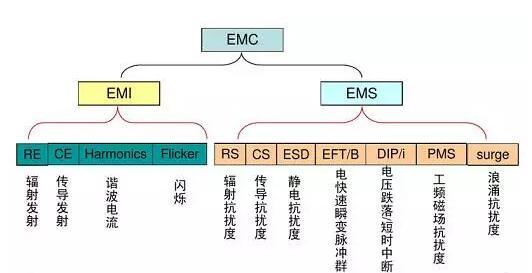
EMC (Electro Magnetic Compatibility): Literally translated as “electromagnetic compatibility”, it refers to the ability of the electromagnetic energy generated by the equipment to neither interfere with other equipment, nor to interfere with the electromagnetic energy of other equipment. EMC includes EMI and EMS.
EMI (Electro Magnetic Interference): Literally translated as electromagnetic interference, it refers to the electromagnetic disturbance it emits to the outside world. This is a compound word, we should consider “electromagnetic” and “interference” separately. The so-called “interference” refers to the two-layer meaning of the performance degradation of equipment after interference and the source of interference to the equipment. The first meaning is like thunder and lightning causing noise on the radio, snowflakes appearing on the TV screen after a motorcycle is driving nearby, and radio sounds are heard after picking up the phone, etc.
EMS (Electro Magnetic Susceptibility): Literally translated as “electromagnetic susceptibility”, it means the ease with which electromagnetic energy can cause performance degradation. To make it easy to understand, we compare electronic devices to people, and electromagnetic energy to cold viruses. Sensitivity is whether or not you are susceptible to catching a cold. If you are not susceptible to catching a cold, it means that you have strong immunity, which is the English word Immunity, which means strong resistance to electromagnetic interference.
EMC test items
Multimedia EMC standards
EN IEC 61000-3-2:2019 EN 61000-3-3:2013/A1:2019 EN 55032:2015/A11:2020 EN 55035:2017 or EN 55024:2010/A1:2015
Home appliances EMC standards
EN IEC 61000-3-2:2019 EN 61000-3-3:2013/A1:2019 EN 55014-1:2017 EN 55014-2-2015
Lamps EMC standard
EN IEC 61000-3-2:2019 EN 61000-3-3:2013/A1:2019 EN 55015:2013+A1:2015 EN 61547:2009
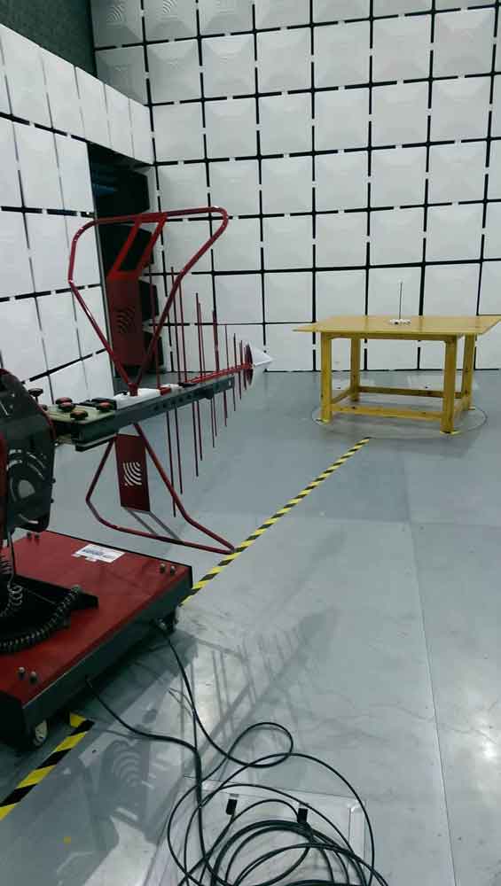
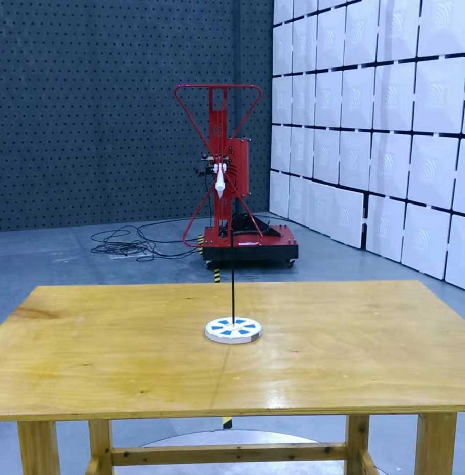
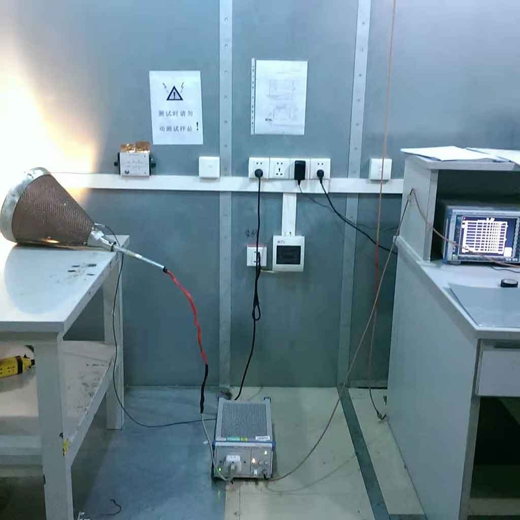
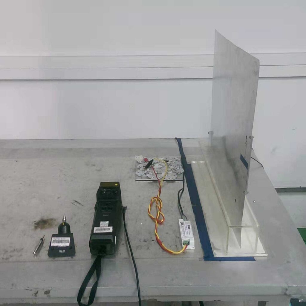
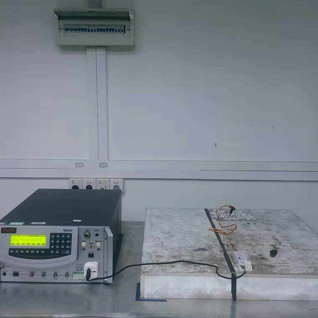
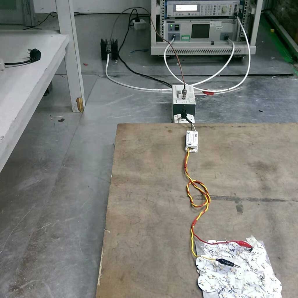
RE testCE testESD testsurge & EFT & dips testCS test
You are welcome to consult us, please contact David Zeng info@emc.wiki or 1513888718@qq.com , We can provide one-stop testing, EMC debug and certification services.
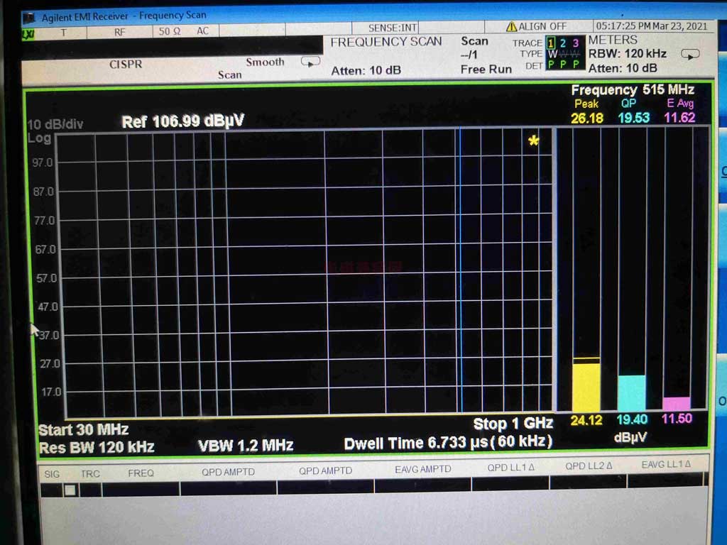
PK, QP, and AV in emc test refer to three different detectors in EMI test receiver or spectrum analyzer.
From the three column diagrams in the above figure, it can be seen that from left to right, the PK detector reading value, the QP detector reading value, and the AV detector reading value are respectively decremented. The reading of the same frequency point is detected by different detectors, in which the PK value is the largest and the AV value is the smallest.
PK> QP> AV
Detector for EMI measurement — PK peak detector, QP quasi-peak detector, AV average detector
The use of quasi-peak detection is a characteristic of civil electromagnetic disturbance emission testing. Since civil electromagnetic compatibility product family standards are all converted from CISPR standards, these standards are compiled to ensure the smooth flow of communication and broadcasting. Therefore, harassment has an impact on communication and broadcasting. The influence of is ultimately judged by human subjective auditory effects. Average detection and peak detection are not enough to describe the impact of pulse amplitude, width and frequency on vision. Quasi-peak detection must be used. Only quasi-peak detection is more consistent. The human ear responds to sounds regularly.
The respective characteristics of several detection methods:
PK peak detection: Its charging time constant is very small, even a very narrow pulse can be quickly charged to a stable value. After the intermediate frequency signal disappears, due to the large discharge time constant of the circuit, the output voltage of the detection can be Stay at the peak for a long time. The feature of peak detection is first used in the harassment emission test of military equipment, because many military equipment can cause explosions or malfunctions of digital equipment as long as a single pulse is stimulated, and there is no need to pay attention to the accumulation of time like audio equipment. The PK value mainly considers the pulse amplitude or the larger peak-to-peak pulse measurement value!
QP quasi-peak detector: The time constant of the impulse and discharge point of this detector is between the average value and the peak value. The output of the detector during the measurement period is not only related to the pulse amplitude, but also related to the pulse repetition frequency, and its output is related to Interference has the same effect on hearing. The magnitude of the QP value will be considered for the pulse amplitude and pulse repetition rate. For example, the PK amplitude of the motor characteristic is often very high, but the radiation is still qualified. That is because the pulse repetition rate of the same frequency of the disturbance signal of the motor is relatively high. Low, so QP is often qualified under certain circumstances. Therefore, if the PK value exceeds the standard, the reading point QP may not necessarily exceed the standard.
AV average detector: Its biggest feature is that the detector has the same charge and discharge time constant, which is especially suitable for continuous wave measurement. The main consideration of the AV value is that the measured value of the pulse with a high repetition rate is relatively large!
The main problems and improvement measures of quasi-peak test The main problem with the quasi-peak detection method for testing is the long measurement time.
Because the quasi-peak measurement takes a long time and the efficiency of the test is relatively low, as an improvement, the peak detector is commonly used for the first round of testing in practice, because among the three types of detection, the measured value obtained by the peak detector should be the highest. If the first round of measurement If the value is lower than the quasi-peak value and the average value given by the standard, then the subsequent test does not need to be performed, and it can be determined that the test has passed. If part of the measured value in the peak test is higher than the standard quasi-peak value and average value, then take the excess frequency band to do the quasi-peak value and average value test. Even so, the entire test time is shorter than all the quasi-peak value and average value. Value detection test.
PK peak detector For EMI measurement, a peak detector is used for preliminary measurement. The measurement speed of peak detection mode is faster than other modes. The signal is usually displayed in peak mode on a spectrum analyzer or EMC analyzer. Since the amplitude of the signal measured in the peak mode is always greater than or equal to the value measured in the quasi-peak or average mode, it is very easy to scan once and compare the result with the limit line. If all signals are below the limit line, the product has already complied with the regulations and no further testing is required.
Characteristics of peak detector The IF circuit part of the EMC analyzer has an envelope or peak detector whose time constant can ensure that the output voltage of the detector always tracks the peak change of the IF signal. In other words, the detector tracks the changes in the envelope of the IF signal, rather than the instantaneous value of the IF sine wave.
QP quasi-peak detector Most of the measurement limit lines for radiation and conduction are based on the quasi-peak detection mode. The quasi-peak detector gives different weight values according to the repetition frequency of the signal, which is also a method of measuring its interference factor. As the signal repetition frequency increases, the quasi-peak detector does not have time to discharge completely, resulting in an increase in output voltage. For continuous wave signals, the measurements of peak detection and quasi-peak detection are the same. Since the reading of the quasi-peak detector is always less than or equal to the peak detector, why not use the quasi-peak detector? Isn’t it easier to pass the EMI test? It is indeed easier to pass the test by doing this, but the quasi-peak detector measurement is faster than the peak detector measurement It was 2 to 3 orders of magnitude slower.
Characteristics of quasi-peak detector The charging speed of the quasi-peak detector is much faster than the discharge speed. Therefore, the higher the signal repetition rate, the higher the output voltage of the quasi-peak detector. The quasi-peak detector can linearly respond to signals of different amplitudes. A signal with high amplitude and low repetition rate may have the same output as a signal with low amplitude and high repetition rate.
AV average detector Certain conducted emission measurements require the use of an average detector with a quasi-peak detector. In addition, the measurement of radiated emissions above 1 GHz is also carried out using an average detector. The output of the average detector is always less than or equal to the output of the peak detector. Characteristics of average detector Average detection is similar to peak detection in many respects. The output of the envelope detector is the modulation envelope. When the post-detection bandwidth is greater than the resolution bandwidth, peak detection is performed. If average detection is to be performed, the detected signal must pass through a filter with a bandwidth much smaller than the resolution bandwidth. This filter averages the high frequency components (such as noise) of the signal output by the envelope detector.
RMS average detector The weight detector used by the RMS average weight receiver is a root mean square detector (applicable to pulse repetition frequencies higher than the corner frequency fc) and an average detector (applicable to pulse repetition frequencies lower than the corner frequency fc). In combination, the following characteristics of the impulse response curve are obtained: 10 dB/decade when higher than the corner frequency, and 20 dB/decade when lower than the corner frequency. See CISPR 16-1-1 2010 for specific response characteristics.
The reading law of several detection methods: PK> QP> AV If the PK value readings are lower than the QP and AV limits, then the standard defaults that there is no need to read the QP value, and it is directly qualified. Therefore, most of the time everyone has to directly qualify for the PK margin. Because QP and AV cannot be higher than PK. If the PK value is higher than the QP value limit, then a QP reading point is required. If the QP reading point can be qualified, then the product is still judged to be qualified. For conduction testing, for example, in the frequency band of 150kHz~30MHz, the standard requires both QP and AV values to be qualified. If one of the frequency points is unqualified, then the entire conduction is unqualified. Why do you want to read QP? That is because the limit required by the standard is the QP value, and the PK value is the read value of the pre-scan.
CISPR 32:2015 is available as CISPR 32:2015 RLV which contains the International Standard and its Redline version, showing all changes of the technical content compared to the previous edition.
CISPR 32:2015 applies to multimedia equipment (MME) as defined in 3.1.24 and having a rated r.m.s. AC or DC supply voltage not exceeding 600 V. This publication covers two classes of MME (Class A and Class B). The MME classes are specified in Clause 4. The objectives of this publication are: 1) to establish requirements which provide an adequate level of protection of the radio spectrum, allowing radio services to operate as intended in the frequency range 9 kHz to 400 GHz; 2) to specify procedures to ensure the reproducibility of measurement and the repeatability of results. This second edition cancels and replaces the first edition published in 2012. This edition constitutes a technical revision. The contents of the corrigendum of June 2016 have been included in this copy.
WHAT IS ELECTROMAGNETIC COMPATIBILITY (EMC) TESTING?
Electromagnetic compatibility (EMC) testing measures the ability of equipment or systems to function satisfactorily in their electromagnetic environment without introducing intolerable electromagnetic disturbance to anything in that environment.
WHY IS EMC TESTING IMPORTANT?
EMC certifications are a mandatory requirement in most markets, including Europe, the US, China, Korea, Australia and New Zealand. EMC testing is necessary to help you meet regulatory requirements, improve product performance and reduce the risk of costly non-compliance. A third-party EMC test lab can conduct conformity assessments and also help to strengthen your competitive position in the market.
A ONE-STOP SERVICE FOR EMC TESTING AND CERTIFICATION
GZSA experts offer comprehensive testing and certification based on their complete knowledge of EMC legislation, guidelines, and standards. Our testing can cover all types of products, from small appliances to large defence industry machines.
We assist you to resolve any EMC regulatory issues, from design concept to final production. We provide a one-stop service that covers all your testing and certification needs. Our experts provide project management to ensure that your EMC tests run smoothly.
You can choose to have tests performed at our labs, on your premises or anywhere your product is installed.
EMC TESTING PROCEDURE
Our worldwide labs are capable of conducting a comprehensive range of EMC tests and providing you with EMC certifications. Depending on your product, this might include:
Antenna immunity to RF voltage
Antenna input immunity
Antenna screening effectiveness
Conducted disturbances immunity
Conducted emissions (continuous and discontinuous interference)
Electrostatic discharge (ESD) immunity
Electrical disturbances from conduction and coupling immunity for vehicles
Electrical fast transient / burst immunity
Harmonic current emission
Harmonics and interharmonics immunity
Immunity from radiated fields
Immunity to induced voltages
On-site EMC testing
Power frequency magnetic field / oscillatory waves immunity
Power interference
Power supply conditioning
Radiated emissions
Radiated field immunity
Voltage fluctuation / flicker
Voltage surge immunity
Voltage dips / interruptions immunity
Magnetic filed measurement (EMF)
Electric field measurement (EMF)
Electromagnetic field measurement (EMF)
Induced current density due to the electric field (EMF for lightning equipment)
All electric devices or installations influence each other when interconnected or close to each other, e.g. interference between TV sets, GSM handsets, radios and nearby washing machine or electrical power lines. The purpose of electromagnetic compatibility (EMC) is to keep all those side effects under reasonable control. EMC designates all the existing and future techniques and technologies for reducing disturbance and enhancing immunity.
The electromagnetic compatibility (EMC) Directive 2014/30/EU ensures that electrical and electronic equipment does not generate, or is not affected by, electromagnetic disturbance.