FCC SDOC

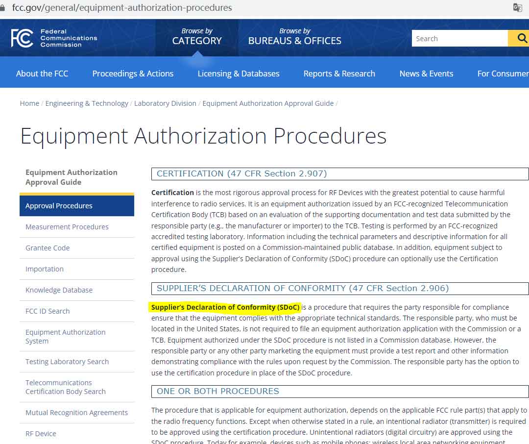
The United States FCC SDOC refers to Supplier’s Declaration of Conformity, or Supplier’s Declaration of Conformity, or SDoC for short. The equipment supplier (note: the supplier must be a local company in the United States) will test the equipment that meets the specified standards or requirements, and the equipment that meets the regulations must provide relevant documents (such as SDoC declaration documents) to provide proof to the public. The SDoC policy simplifies the previously complicated FCC certification requirements and further reduces the burden on enterprises.
FCC SDOC

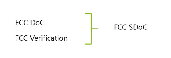
SDOC certification means that all electronic and electrical products going to the United States need to comply with FCC PART 15B of the United States, that is, all previous electronic and electrical products that comply with FCC VoC and FCC DoC.

FCC SDoC changes

  • There are clear requirements for the person in charge of the product, and the contact information of the U.S. company needs to be provided. The responsible party can be the importer or consignee or customs broker. At the same time, after November 2, 2018, the FCC DOC and FCC VOC will be invalid;
  • All SDoC products can independently choose whether to mark the FCC Logo;
  • The authentication methods of our common equipment have undergone major changes. Except for wireless transmission products/scanning receivers/power line broadband access/radar detection products, FCC ID must be made, and all other products can choose FCC ID or SDOC.

SDoC product range

In applying for FCC certification, FCC SDoC applies to ordinary products without wireless functions, such as displays, ordinary household appliances, lamps, etc. Including personal computers and peripheral equipment; household appliances; electric tools; audio and video products; lamps; toys; security products, etc. Such as monitors, mice, refrigerators, electric kettles, hair dryers, LED lamps, electronic toys, ordinary access control and other products.

FCC Class A or B

§ 15.3 Definitions.

(h) Class A digital device. A digital device that is marketed for use in a commercial,industrial or business environment,exclusive of a device which is marketed for use by the general publicor is intended to be used in the home.

(i) Class B digital device. A digital device that is marketed for use in a residential environment notwithstanding use in commercial, business and industrial environments. Examples of such devices include, but are not limited to, personal computers, calculators, and similar electronic devices that are marketed for use by the general public.

NOTE: The responsible party may also qualify a device intended to be marketed in a commercial, business or industrial environment as a Class B device, and in fact is encouraged to do so, provided the device complies with the technical specifications for a Class B digital device. In the event that a particular type of device has been found to repeatedly cause harmful interference to radio communications, the Commission may classify such a digital device as a Class B digital device, regardless of its intended use.

FCC SDOC conducted emission limit

§15.107 Conducted limits.

(a) Except for Class A digital devices, for equipment that is designed to be connected to the public utility (AC) power line, the radio frequency voltage that is conducted back onto the AC power line on any frequency or frequencies within the band 150 kHz to 30 MHz shall not exceed the limits in the following table, as measured using a 50 μH/50 ohms line impedance stabilization network (LISN). Compliance with the provisions of this paragraph shall be based on the measurement of the radio frequency voltage between each power line and ground at the power terminal. The lower limit applies at the band edges.

Frequency of emission (MHz)Conducted limit (dBμV)Conducted limit (dBμV)
Quasi-peakAverage
0.15-0.566 to 56*56 to 46*
0.5-55646
5-306050

(b) For a Class A digital device that is designed to be connected to the public utility (AC) power line, the radio frequency voltage that is conducted back onto the AC power line on any frequency or frequencies within the band 150 kHz to 30 MHz shall not exceed the limits in the following table, as measured using a 50 μH/50 ohms LISN. Compliance with the provisions of this paragraph shall be based on the measurement of the radio frequency voltage between each power line and ground at the power terminal. The lower limit applies at the boundary between the frequency ranges.

Frequency of emission (MHz)Conducted limit (dBμV)Conducted limit (dBμV)
Quasi-peakAverage
0.15-0.57966
0.5-307360

FCC SDOC Radiation Test Limit Request

§15.109 Radiated emission limits.

(a) Except for Class A digital devices, the field strength of radiated emissions from unintentional radiators at a distance of 3 meters shall not exceed the following values:

Frequency of emission (MHz)Field strength (microvolts/meter)
30-88100
88-216150
216-960200
Above 960500

(b) The field strength of radiated emissions from a Class A digital device, as determined at a distance of 10 meters, shall not exceed the following:

Frequency of emission (MHz)Field strength (microvolts/meter)
30-8890
88-216150
216-960210
Above 960300

Typical question and answer

  1. Should the lighting products be grade A or grade B? Answer: According to the standard lamps, if they are installed in the home, they must meet the B-level limit requirements. If they are installed in outdoor or industrial environments, they can use the A-level limit requirements.
  2. Is FCC Part 15 Grade B easy to pass, or is FCC Part 15 Grade A easy to pass? Answer: According to the limits stipulated in the standard, the limit of Class A is significantly higher than the limit of Class B, which means that Class A is easier to pass in the case of the same sample.
  3. Can FCC test data of A and B levels be interchangeable? If the data is tested to level B, if level B does not meet the requirements, can it be replaced with level A? Answer: Of course, it can be interchanged. The data will not change. Only the limit value is changed. Generally, the test software can easily exchange the A-level and B-level limits. Please confirm and communicate with the test engineer. For example, if you are taller than Yao Ming and taller than Zhangwei, your height remains the same, and what you change is just a reference.

You are welcome to consult us, please contact David Zeng info@emc.wiki or 1513888718@qq.com , We can provide one-stop testing, EMC debug and certification services.
FCC ID

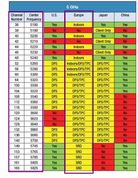
WIFI 5G band

FCC ID refers to the FCC wireless certification in the United States. After passing the certification, a string of numbers will appear, commonly known as FCC ID certification.

FCC

FCC ID products include

Wireless radio frequency products, such as BT, Wifi, Zigbee, 2.4GHz, 5GHz, mobile phone products, various remote controls and other intentional launch products, all need to comply with the US FCC PART 15C standard limit.

Verification method

  • The product needs to pass the FCC approved test lab with the test is completed and the test report is obtained.
  • Organize product technical information, including: product details photos, block diagrams, circuit schematics, operational description, user manuals, etc.
  • Then the NVLAP & A2LA test laboratory approved by the FCC will submit it to the FCC TCB test room to confirm that all the information is correct (or directly find the TCB), and issue a certificate.

FCC ID standard

  • FCC ID 47 CFR PART 15 Subpart C: 2019 section 15.247 (not 5g wifi)
  • ANSI C63.10: 2013

Coverage frequency

  • FCC Rules and Regulations Part 15 Subpart C Section 15.247-2.4G WIFI / BT
  • FCC Rules and Regulations Part 15 Subpart C Section 15.407-5.2G WiFi
  • FCC Rules and Regulations Part 15 Subpart C Section 15.407-5.8G WiFi
  • For MIMO system of 802.11n/ac, total power is calculated by combining the output power of each antenna according to KDB662911

North America 2.4G BT

2402-2480 MHz

  • GFSK, π/4-DQPSK, 8DPSK for Bluetooth (DSS)
  • GFSK for Bluetooth (DTS)
  • 79 channels for Bluetooth (DSS)
  • 40 channels for Bluetooth (DTS)

North America 2.4G WIFI

2412MHz ~ 2462MHz

802.11b: DSSS; 802.11g/n: OFDM

  • 11 Channel for 20MHz bandwidth(2412~2462MHz)
  • 7 channels for 40MHz bandwidth(2422~2452MHz)

North America 5G WIFI frequency band

  • 5150 MHz ~ 5250 MHz
  • 5725 MHz ~ 5850MHz

FCC Part 15.407: Unlicensed National Information Infrastructure (U-NII)

North America 5.2G WIFI

FCC Rules and Regulations Part 15 Subpart C Section 15.407

ANSI C63.10: 2013

  • 4 channels for 5180 MHz ~ 5240 MHz (802.11a/n/ac-HT20);
  • 2 channels for 5190 MHz ~ 5230 MHz (802.11n/ac-HT40);
  • 1 channel for 5210 MHz (802.11ac-HT80);

North America 5.8G WIFI

FCC Rules and Regulations Part 15 Subpart C Section 15.407
ANSI C63.10: 2013

  • 5 channels for 5745 MHz ~ 5825 MHz (802.11a/n/ac-HT20);
  • 2 channels for 5755 MHz ~ 5795 MHz (802.11n/ac-HT40);
  • 1 channel for 5775 MHz (802.11ac-HT80);

North American DFS Band

If you have a device that supports WIFI 802.11a, you need to evaluate DFS, which includes Master active such as a router, and Slave passive such as a mobile phone.

  • 5.250–5.350 GHz, whether it is used indoors or outdoors, should be operated according to dynamic frequency selection (DFS or avoid radar). The regulations allow users to install antennas with a power limit of 250 mW.
  • 5.470-5.725 GHz, whether it is used indoors or outdoors, should be operated according to dynamic frequency selection (DFS or avoid radar).

FCC ID certification sample preparation

  • Provide at least 1~2 prototypes required to apply for FCC ID, one complete and ordinary similar shipment sample, and one RF fixed-frequency prototype.
  • 1~2 sets of complete samples
  • 1~2 sets of fixed frequency prototypes
  • Fixed frequency software
  • Fixed frequency method

FCC ID certificate official query

https://apps.fcc.gov/oetcf/eas/reports/GenericSearch.cfm

You are welcome to consult us, please contact David Zeng info@emc.wiki or 1513888718@qq.com , We can provide one-stop testing, rectification and certification services.

.

CE certification

We can provide customers with CE certification for various electronic and electrical products.

Not limited to Electromagnetic compatibility (EMC) DIRECTIVE 2014/30/EU, Radio Equipment (RED) Directive 2014/53/EU,Low Voltage (LVD) Directive 2014/35/EU,Restriction of the use of certain hazardous substances (RoHS) Directive 2011/65/EU.

CE-certification
CE-certification

EMC – Electromagnetic compatibility – DIRECTIVE 2014/30/EU

Multimedia EMC standards

EN IEC 61000-3-2:2019
EN 61000-3-3:2013/A1:2019
EN 55032:2015/A11:2020
EN 55035:2017 or EN 55024:2010/A1:2015

Home appliances EMC standards

EN IEC 61000-3-2:2019
EN 61000-3-3:2013/A1:2019
EN 55014-1:2017
EN 55014-2-2015

Lamps EMC standard

EN IEC 61000-3-2:2019
EN 61000-3-3:2013/A1:2019
EN 55015:2013+A1:2015
EN 61547:2009

RED – Radio Equipment – Directive 2014/53/EU

For Bluetooth wireless products, what standards are required for European wireless RED certification?

RF (intentionally radiated radio frequency part)

  • EN 300328 V2.2.2
  • EN 301489-1 V2.2.3
  • EN 301489-17 V3.2.2

EMC (Unintentional emission part, according to different products, different product standards are used, the following is an example of Bluetooth speakers)

  • EN IEC 61000-3-2:2019
  • EN 61000-3-3:2013/A1:2019
  • EN 55032:2015/A11:2020
  • EN 55035:2017 or EN 55024:2010/A1:2015

LVD (Low Voltage Directive, choose one of the following two)

  • EN 62368-1:2014+A11:2017
  • or
  • EN 60950

EMF

  • EN 62479:2010

European WIFI test standard

RED Radio Frequency RF Standard

  • EN 300328 V2.2.2(For 2.4GHz)
  • ETSI EN 301 893 V2.1.1(For 5GHz)
  • EN 301489-1 V2.2.3
  • EN 301489-17 V3.2.2

If it is embedded in a certain type of product, it needs to meet the corresponding product standards. For example, multimedia products need to meet:

EMC standards

  • EN IEC 61000-3-2:2019
  • EN 61000-3-3:2013/A1:2019
  • EN 55032:2015/A11:2020
  • EN 55035:2017 or EN 55024:2010/A1:2015

There are also safety standards corresponding to the LVD directive. For example, multimedia products need to meet: EN 62368-1

LVD (Low Voltage Directive, choose one of the following two)

  • EN 62368-1:2014+A11:2017
  • EN 60950

EMF

  • EN IEC 62311:2020

You are welcome to consult us, please contact David Zeng info@emc.wiki or 1513888718@qq.com , We can provide one-stop testing, rectification and certification services.

EMC debug

EMI debug

We can provide customers with EMC of various electronic and electrical products debug services.

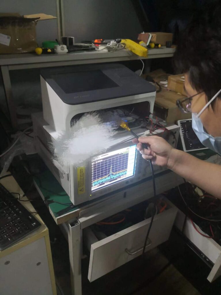
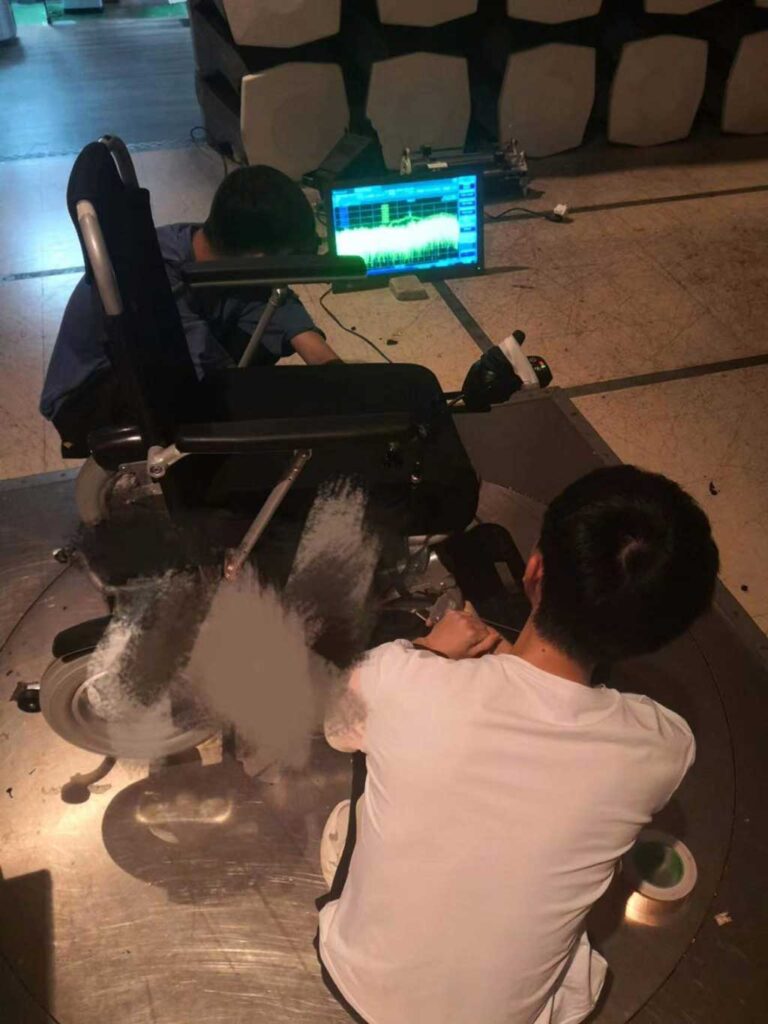
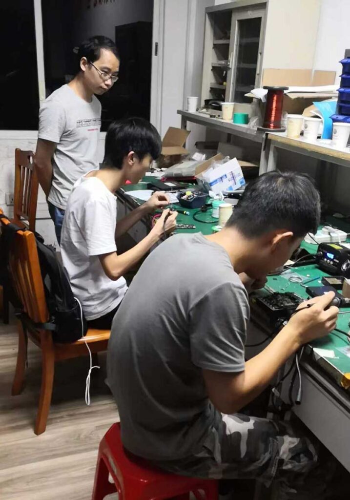
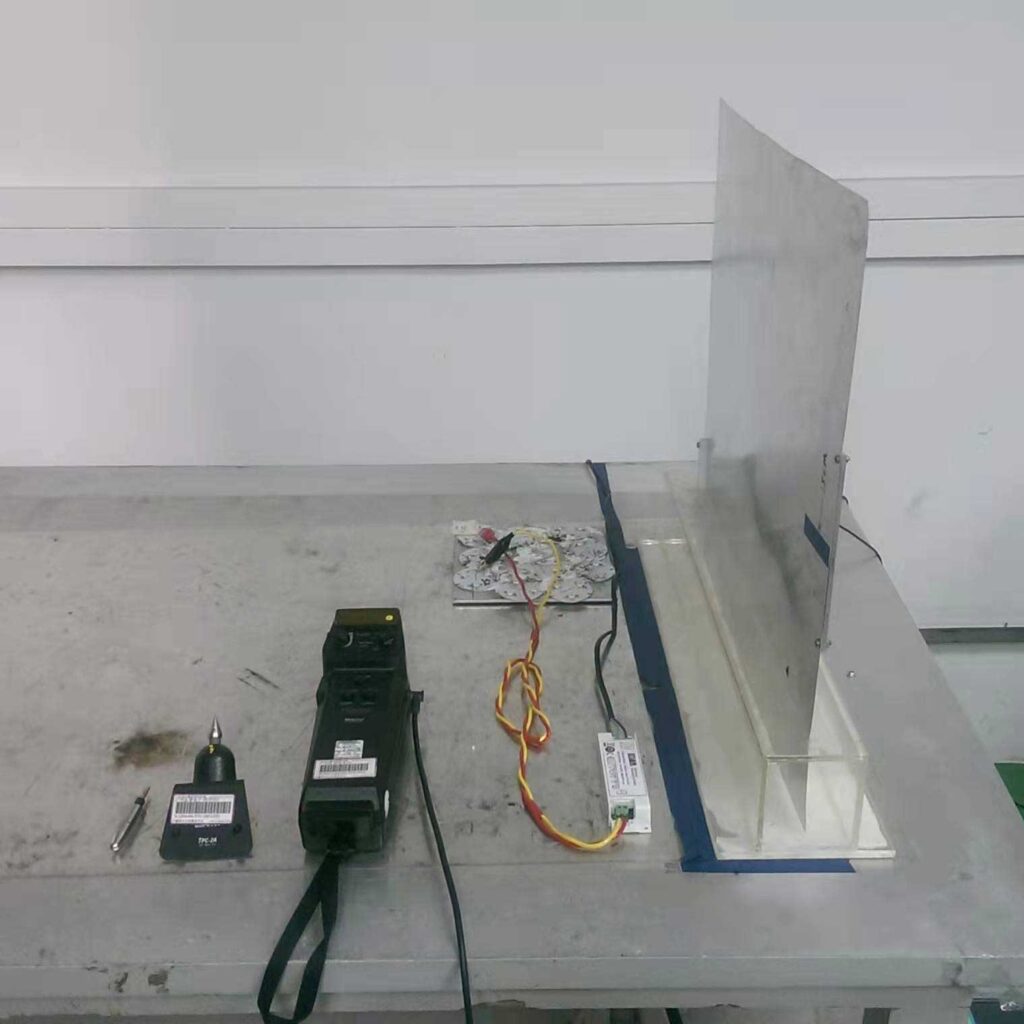
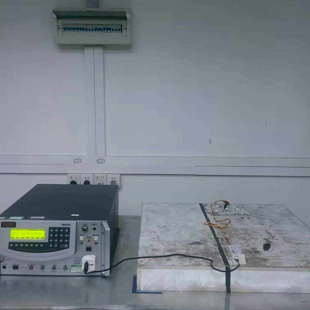
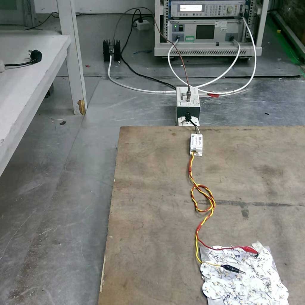
For example, the product radiated emission exceeds the standard limit, the conducted emission exceeds the standard limit, the ESD anti-interference does not meet the standard requirements, the RS radiation anti-interference does not meet the standard requirements, the surge immunity does not meet the standard requirements, and the CS conduction immunity does not meet the standard requirements. Meet the standard requirements, etc. We can all help customers to debug, for example, add lc filtering on pcb, change capacitance, inductance parameter value, pcb trace for wire cutting and jumper, cable shielding, adding EMI magnetic ring, etc.

EMI debug
EMC debug
EMC debug
EMI and EMS Debug
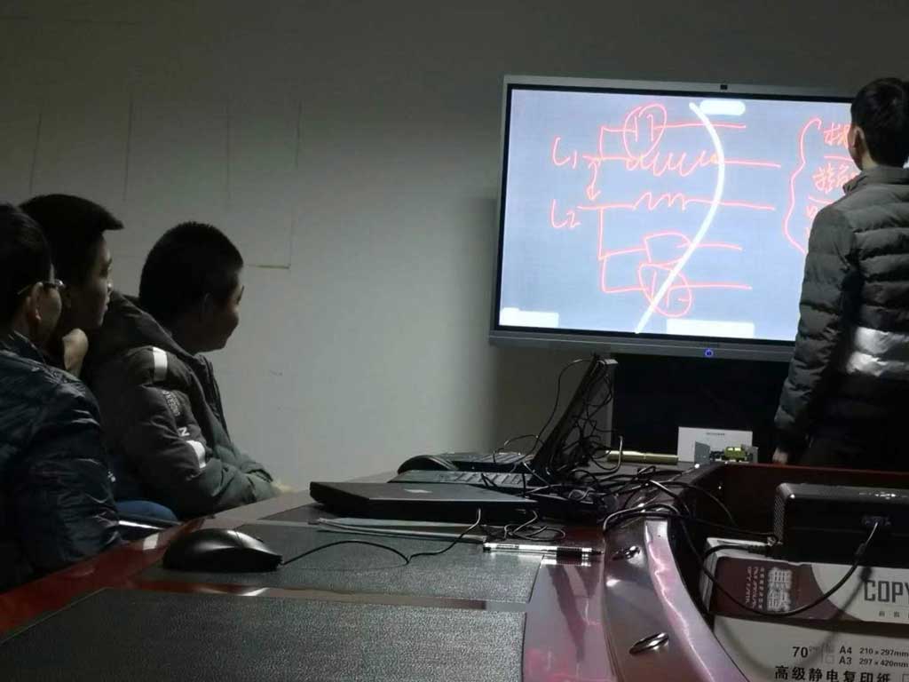
Meeting to study EMC issues

You are welcome to consult us, please contact David Zeng info@emc.wiki or 1513888718@qq.com , We can provide one-stop testing, EMC debug and certification services.
EMC Testing

What is EMC?

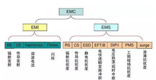
EMC (Electro Magnetic Compatibility): Literally translated as “electromagnetic compatibility”, it refers to the ability of the electromagnetic energy generated by the equipment to neither interfere with other equipment, nor to interfere with the electromagnetic energy of other equipment. EMC includes EMI and EMS.

EMI (Electro Magnetic Interference): Literally translated as electromagnetic interference, it refers to the electromagnetic disturbance it emits to the outside world. This is a compound word, we should consider “electromagnetic” and “interference” separately. The so-called “interference” refers to the two-layer meaning of the performance degradation of equipment after interference and the source of interference to the equipment. The first meaning is like thunder and lightning causing noise on the radio, snowflakes appearing on the TV screen after a motorcycle is driving nearby, and radio sounds are heard after picking up the phone, etc.

EMS (Electro Magnetic Susceptibility): Literally translated as “electromagnetic susceptibility”, it means the ease with which electromagnetic energy can cause performance degradation. To make it easy to understand, we compare electronic devices to people, and electromagnetic energy to cold viruses. Sensitivity is whether or not you are susceptible to catching a cold. If you are not susceptible to catching a cold, it means that you have strong immunity, which is the English word Immunity, which means strong resistance to electromagnetic interference.

EMC test items

Multimedia EMC standards

EN IEC 61000-3-2:2019
EN 61000-3-3:2013/A1:2019
EN 55032:2015/A11:2020
EN 55035:2017 or EN 55024:2010/A1:2015

Home appliances EMC standards

EN IEC 61000-3-2:2019
EN 61000-3-3:2013/A1:2019
EN 55014-1:2017
EN 55014-2-2015

Lamps EMC standard

EN IEC 61000-3-2:2019
EN 61000-3-3:2013/A1:2019
EN 55015:2013+A1:2015
EN 61547:2009

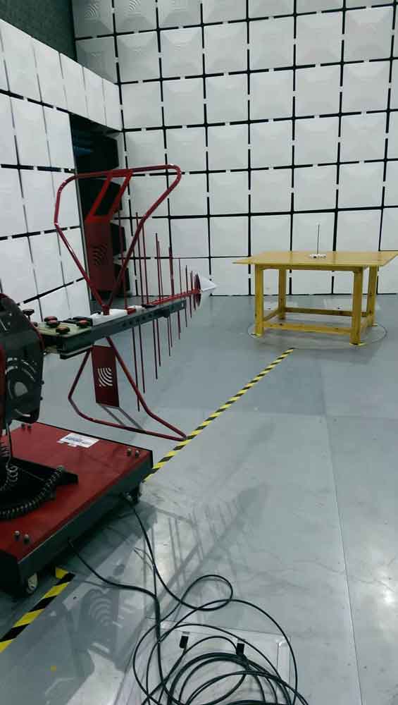
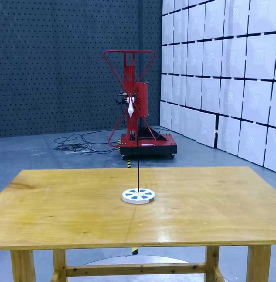
RE test
RE test
CE test
CE test
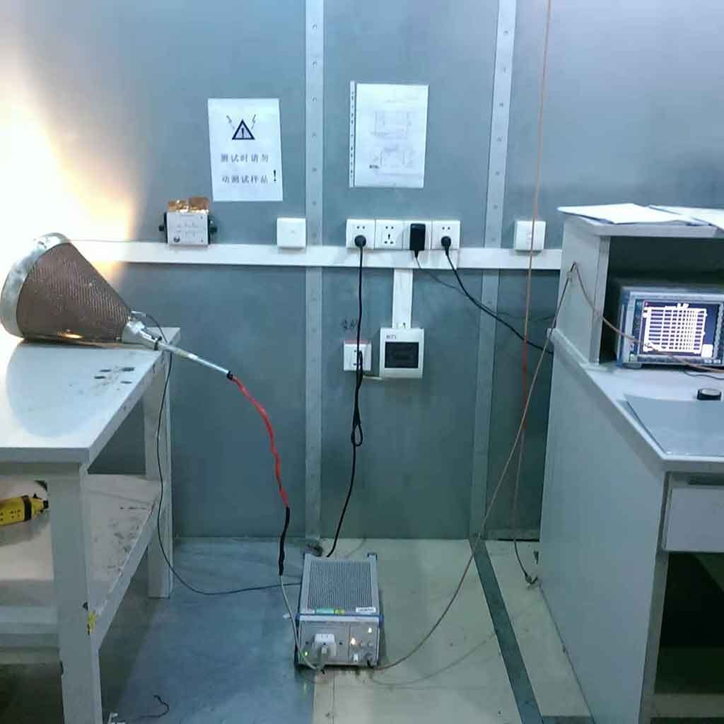
ESD test
ESD test
surge & EFT & dips test

CS test
CS test

You are welcome to consult us, please contact David Zeng info@emc.wiki or 1513888718@qq.com , We can provide one-stop testing, EMC debug and certification services.
SRRC certification

State Radio Regulatory Commission of the People’s Republic of China

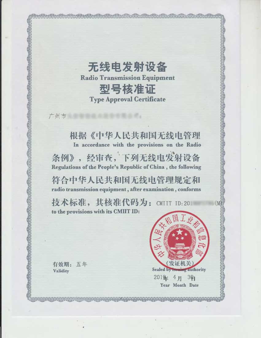
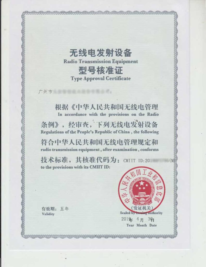
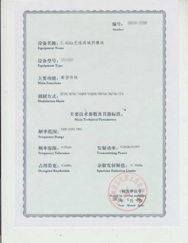
SRRC is a mandatory certification requirement of the National Radio Regulatory Commission. Since June 1, 1999, the Ministry of Information Industry (MII) of China has mandated that all radio component products sold and used in China must obtain a radio model Radio Type Approval Certification (Radio Type Approval Certification).

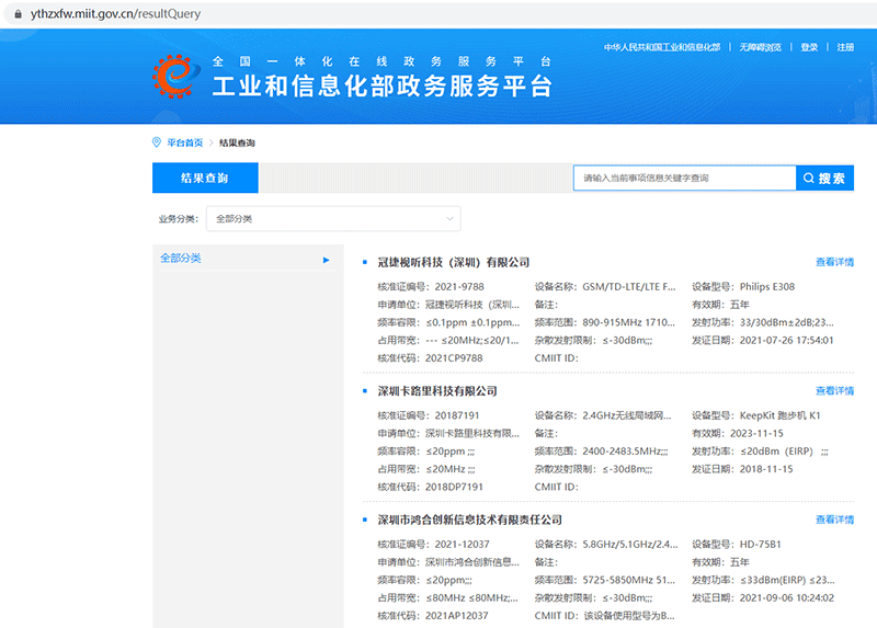
At present, China’s SRRC certification is all managed and issued by the Ministry of Industry and Information Technology of the People’s Republic of China.

Wireless products sold in the Chinese market must apply for SRRC certification as long as they are in the SRRC product catalog. For example, Bluetooth, wifi, zigbee, 2g, 3g, 4g, 5g products are typical SRRC compulsory certification products.

We have an RF testing laboratory in Guangzhou, which can provide customers with pre-testing, data sorting, registration with the Ministry of Industry and Information Technology of China, and one-stop SRRC testing and certification services.

You are welcome to consult us, please contact David Zeng info@emc.wiki or 1513888718@qq.com , We can provide one-stop testing, EMC debug and certification services.

What are PK, QP, AV in EMC test?

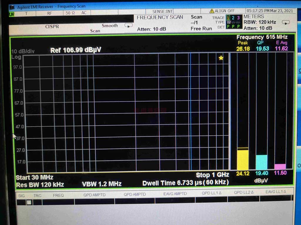
PK, QP, and AV in emc test refer to three different detectors in EMI test receiver or spectrum analyzer.

From the three column diagrams in the above figure, it can be seen that from left to right, the PK detector reading value, the QP detector reading value, and the AV detector reading value are respectively decremented. The reading of the same frequency point is detected by different detectors, in which the PK value is the largest and the AV value is the smallest.

PK> QP> AV

Detector for EMI measurement — PK peak detector, QP quasi-peak detector, AV average detector

The use of quasi-peak detection is a characteristic of civil electromagnetic disturbance emission testing. Since civil electromagnetic compatibility product family standards are all converted from CISPR standards, these standards are compiled to ensure the smooth flow of communication and broadcasting. Therefore, harassment has an impact on communication and broadcasting. The influence of is ultimately judged by human subjective auditory effects. Average detection and peak detection are not enough to describe the impact of pulse amplitude, width and frequency on vision. Quasi-peak detection must be used. Only quasi-peak detection is more consistent. The human ear responds to sounds regularly.

The respective characteristics of several detection methods:

  1. PK peak detection: Its charging time constant is very small, even a very narrow pulse can be quickly charged to a stable value. After the intermediate frequency signal disappears, due to the large discharge time constant of the circuit, the output voltage of the detection can be Stay at the peak for a long time. The feature of peak detection is first used in the harassment emission test of military equipment, because many military equipment can cause explosions or malfunctions of digital equipment as long as a single pulse is stimulated, and there is no need to pay attention to the accumulation of time like audio equipment. The PK value mainly considers the pulse amplitude or the larger peak-to-peak pulse measurement value!
  2. QP quasi-peak detector: The time constant of the impulse and discharge point of this detector is between the average value and the peak value. The output of the detector during the measurement period is not only related to the pulse amplitude, but also related to the pulse repetition frequency, and its output is related to Interference has the same effect on hearing. The magnitude of the QP value will be considered for the pulse amplitude and pulse repetition rate. For example, the PK amplitude of the motor characteristic is often very high, but the radiation is still qualified. That is because the pulse repetition rate of the same frequency of the disturbance signal of the motor is relatively high. Low, so QP is often qualified under certain circumstances. Therefore, if the PK value exceeds the standard, the reading point QP may not necessarily exceed the standard.
  3. AV average detector: Its biggest feature is that the detector has the same charge and discharge time constant, which is especially suitable for continuous wave measurement. The main consideration of the AV value is that the measured value of the pulse with a high repetition rate is relatively large!
  4. The main problems and improvement measures of quasi-peak test
    The main problem with the quasi-peak detection method for testing is the long measurement time.

Because the quasi-peak measurement takes a long time and the efficiency of the test is relatively low, as an improvement, the peak detector is commonly used for the first round of testing in practice, because among the three types of detection, the measured value obtained by the peak detector should be the highest. If the first round of measurement If the value is lower than the quasi-peak value and the average value given by the standard, then the subsequent test does not need to be performed, and it can be determined that the test has passed. If part of the measured value in the peak test is higher than the standard quasi-peak value and average value, then take the excess frequency band to do the quasi-peak value and average value test. Even so, the entire test time is shorter than all the quasi-peak value and average value. Value detection test.

PK peak detector
For EMI measurement, a peak detector is used for preliminary measurement. The measurement speed of peak detection mode is faster than other modes. The signal is usually displayed in peak mode on a spectrum analyzer or EMC analyzer. Since the amplitude of the signal measured in the peak mode is always greater than or equal to the value measured in the quasi-peak or average mode, it is very easy to scan once and compare the result with the limit line. If all signals are below the limit line, the product has already complied with the regulations and no further testing is required.

Characteristics of peak detector
The IF circuit part of the EMC analyzer has an envelope or peak detector whose time constant can ensure that the output voltage of the detector always tracks the peak change of the IF signal. In other words, the detector tracks the changes in the envelope of the IF signal, rather than the instantaneous value of the IF sine wave.

QP quasi-peak detector
Most of the measurement limit lines for radiation and conduction are based on the quasi-peak detection mode. The quasi-peak detector gives different weight values ​​according to the repetition frequency of the signal, which is also a method of measuring its interference factor. As the signal repetition frequency increases, the quasi-peak detector does not have time to discharge completely, resulting in an increase in output voltage. For continuous wave signals, the measurements of peak detection and quasi-peak detection are the same. Since the reading of the quasi-peak detector is always less than or equal to the peak detector, why not use the quasi-peak detector? Isn’t it easier to pass the EMI test? It is indeed easier to pass the test by doing this, but the quasi-peak detector measurement is faster than the peak detector measurement It was 2 to 3 orders of magnitude slower.

Characteristics of quasi-peak detector
The charging speed of the quasi-peak detector is much faster than the discharge speed. Therefore, the higher the signal repetition rate, the higher the output voltage of the quasi-peak detector. The quasi-peak detector can linearly respond to signals of different amplitudes. A signal with high amplitude and low repetition rate may have the same output as a signal with low amplitude and high repetition rate.

AV average detector
Certain conducted emission measurements require the use of an average detector with a quasi-peak detector. In addition, the measurement of radiated emissions above 1 GHz is also carried out using an average detector. The output of the average detector is always less than or equal to the output of the peak detector.
Characteristics of average detector
Average detection is similar to peak detection in many respects. The output of the envelope detector is the modulation envelope. When the post-detection bandwidth is greater than the resolution bandwidth, peak detection is performed. If average detection is to be performed, the detected signal must pass through a filter with a bandwidth much smaller than the resolution bandwidth. This filter averages the high frequency components (such as noise) of the signal output by the envelope detector.

RMS average detector
The weight detector used by the RMS average weight receiver is a root mean square detector (applicable to pulse repetition frequencies higher than the corner frequency fc) and an average detector (applicable to pulse repetition frequencies lower than the corner frequency fc). In combination, the following characteristics of the impulse response curve are obtained: 10 dB/decade when higher than the corner frequency, and 20 dB/decade when lower than the corner frequency. See CISPR 16-1-1 2010 for specific response characteristics.

The reading law of several detection methods:
PK> QP> AV
If the PK value readings are lower than the QP and AV limits, then the standard defaults that there is no need to read the QP value, and it is directly qualified. Therefore, most of the time everyone has to directly qualify for the PK margin. Because QP and AV cannot be higher than PK.
If the PK value is higher than the QP value limit, then a QP reading point is required. If the QP reading point can be qualified, then the product is still judged to be qualified.
For conduction testing, for example, in the frequency band of 150kHz~30MHz, the standard requires both QP and AV values ​​to be qualified. If one of the frequency points is unqualified, then the entire conduction is unqualified.
Why do you want to read QP? That is because the limit required by the standard is the QP value, and the PK value is the read value of the pre-scan.

Information to be submitted for SRRC certification

SRRC requirements are as follows:
Samples: 6 units are provided(1 set as a backup), of which 4 prototypes need to lead out radio frequency cables. Different RF product samples may have different requirements, but basic BT and WIFI need to provide 6 prototypes.

document:
A. Has the applicant registered an account in the SRRC reporting system? If not, please provide the following information, and our company will help you register; if you have already registered, please provide your account and password.

  1. Color scanned copy of the applicant’s business license (the copy is affixed with the official seal, and the foreign company provides organization certification materials and Chinese translation, and the official seal is added)
  2. A copy of the legal person ID card with official seal
  3. Contact phone number of the handler

B. Application materials (all documents must be in Chinese, and the file size should not exceed 5M):

  1. Application form, letter of commitment, (attached, please fill out and confirm with our company)
  2. Color scanned copy of the applicant’s business license (can be ignored if provided),
  3. Power of attorney with official seal and scanned copy of ID card (see attachment)
  4. If the product is produced by the applicant, provide the applicant’s ISO quality system certificate, if it is not necessary to provide technical capabilities, production capacity and quality assurance system description (including at least the main production equipment model, number or quantity) production line, production plan, Corresponding testing equipment, etc.);
  5. If the applicant entrusts factory production, the contract between the applicant and the factory and the factory’s ISO quality system certificate or system description (including at least the main production equipment model, number of sets or production line, production plan, corresponding testing equipment, etc.);
  6. Block diagram, circuit diagram, product technical manual, RF part BOM (fill in the attachment form), RF module specification, antenna specification;
  7. Nameplate (including applicant name, product model, CMIIT ID: XXXXXXXXXXX, etc.)

Please provide priority in preparation for system registration

  1. Applicant’s business license (color drawing and official seal)
  2. Power of attorney (seal)
  3. A copy of the legal person’s ID card and a copy of the handler’s ID card (color trace and official seal)

For more SRRC details infomation, please contact David Zeng info@emc.wiki or 1513888718@qq.com

SRRC Type Approval and Certification Sample Quantity Requirements

There are often customer inquiries as to how many samples are required for SRRC certification, the type of radio transmission equipment approved, the type of equipment and the number of samples, as detailed below: In principle, the samples mentioned below refer to the complete prototype that has been applied for certification, or the module that has been applied for certification, etc. If the prototype is very large, you can provide a complete prototype according to the requirements of different laboratories, or provide other modules in the form of modules. For details, please contact David Zeng  info@emc.wiki or 1513888718@qq.com

Equipment typeQuantity of samples submittedQuantity of test samplesAccessories and sample requirements
2.4GHz spread spectrum communication equipment53The sample can transmit modulation and carrier signals continuously at a fixed frequency;
Provide detailed frequency list and rate list;
Provide equipment testing software and methods, which can set parameters such as transmit power and frequency;
Provide radio frequency test interface;
Provide the RF test cable and the attenuation value of the applied frequency band, and the antenna gain value;
If there is no serial number on the test sample, it needs to be provided separately.
5.8GHz spread spectrum communication equipment53The sample can transmit modulation and carrier signals continuously at a fixed frequency;
Provide detailed frequency list and rate list;
Provide equipment testing software and methods, which can set parameters such as transmit power and frequency;
Provide radio frequency test interface;
Provide the RF test cable and the attenuation value of the applied frequency band, and the antenna gain value;
2.4GHz band wireless LAN equipment53The sample can transmit modulation and carrier signals continuously at a fixed frequency;
Provide the bandwidth, transmission rate, and transmission channel supported by the device;
Provide RF test interface, number of RF cables and antennas, antenna gain and RF cable attenuation instructions for the applied frequency band; 4. Provide equipment test software, test methods and necessary test tools;
If there is no serial number on the sample sent, the customer needs to provide it separately.
If the type of sample submitted for inspection is a module, a statement of whether the module is restrictive or complete shall be provided;
If the sample submitted for inspection is a complete device made of a module that has been model-approved, in addition to the above information, the device must also meet the conditions for radiation testing, and provide a differentiation statement and the original device and the original module model approval certificate.
For Bluetooth devices, it should clearly support the version (such as 2.0, 4.0, 5.0), mode (such as BR, EDR, LE) and rate. For Bluetooth devices that use the signaling test mode, the tested sample should be adjusted to the signaling test mode. Integrated with Bluetooth
The tester establishes a test connection.
5.8GHz band wireless LAN equipment53The sample can transmit modulation and carrier signals continuously at a fixed frequency;
Provide the bandwidth, transmission rate, and transmission channel supported by the device
Provide radio frequency test interface, radio frequency
Description of the number of cables and antennas, antenna gain, and RF cable attenuation of the applied frequency band;
Provide equipment test software, test methods and necessary test tools, and can set parameters such as transmit power and frequency;
If there is no serial number on the sample sent, the customer needs to provide it separately.
If the type of sample submitted for inspection is a module, a statement of whether the module is restrictive or complete shall be provided;
If the sample submitted for inspection is a complete device made of a module that has been model-approved, in addition to the above information, the device must also meet the conditions for radiation testing, and provide a differentiation statement and the original device and the original module model approval certificate.
GSM terminal53Provide sample radio frequency test interfaces, including schematic diagrams of the positions of the radio frequency test interfaces of each standard of 2G/3G/4G;
Provide RF test cable and attenuation value of the applied frequency band;
The sample can establish a communication connection with the integrated tester through the radio frequency cable, and the integrated tester is controllable
Prepare samples to change radio frequency parameters such as transmit power and working frequency;
At least one sample can establish a communication connection with the comprehensive tester through radiation;
The IMEI number read out via the dial keypad “*#06#” or related software should be consistent with the IMEI number posted on the back of the sample;
Non-mobile phone devices need to provide test accessories needed to ensure the normal operation of the sample (such as setting the operation of opening the mobile network, the command code of the AT command and its software, the schematic diagram of the device serial line connection, the positive and negative poles of the power supply, and the set voltage Value or current value, etc.);
If the device supports the authentication and security function (WAPI), a list of key components related to WAPI should be provided.
Public walkie talkie53The sample can transmit modulation and carrier signals at a fixed frequency;
Provide equipment test software and methods, which can set parameters such as transmit power and frequency; 3. Provide RF test interface;
Provide the attenuation value of the RF test cable and the applied frequency band;
If there is no serial number on the test sample, it needs to be provided separately.
800/900MHz band radio frequency identification (RFID) equipment53The sample can transmit modulation, carrier signal and frequency hopping working signal at a fixed frequency;
Provide equipment testing software and methods, which can set parameters such as transmit power and frequency;
Provide radio frequency test interface;
Provide the attenuation value of the RF test cable and the applied frequency band, and the antenna gain value;
If there is no serial number on the test sample, it needs to be provided separately;
If the type of sample to be inspected is a module, it is necessary to provide a statement whether the module is restrictive or complete.
Internet of Vehicles (Intelligent Connected Cars) Directly Connected Communication Radio Equipment53Provide sample RF test interface, including
2G/3G/4G radio frequency test interface location diagram of each standard;
Provide RF test cable and attenuation value of the applied frequency band;
The sample can establish a communication connection with the integrated tester through the radio frequency cable, and the integrated tester can control the sample to change the transmission power and working frequency.